
IOT ESP8266 Tutorial – Using nodeMCU/LUA
This is the first of a multi-part posting on the ESP8266. We are going to show how to use the ESP8266 IOT WiFi processor and breakout board. We are using this chip for several new IOT projects at SwitchDoc Labs. Our latest IOT project is called LightSwarm and it uses 5 ESP8266 boards arrayed in a cooperative distributed swarm. More on that project in a future posting.
Part 1 IOT ESP8266 Tutorial – Using nodeMCU/LUA
Part 2 IOT ESP8266 Timer Tutorial – Arduino IDE
Part 3 IOT ESP8266 Tutorial – Using the Arduino IDE
Part 4 IOT ESP8266 Tutorial – AT Command Set Firmware
Part 5 IOT ESP8266 Tutorial – Connect to the IBM Bluemix Internet of Things
Part 6 IOT ESP8266 Tutorial – Sending ESP8266 Data to the IBM Bluemix IOT
Part 7 IOT ESP8266 Tutorial – The IOT Application and Source Code
Part 8 IOT ESP8266 Tutorial – Displaying the data on the IBM Bluemix IOT
We are using the Adafruit ESP8266 Huzzah breakout board for these postings.
The ESP8266
The ESP8266 is made by a privately held company in China called Espressif. They are a fabless semiconductor company that just came out of nowhere and shook up the whole industry. Now all the major players are working on inexpensive versions of an IOT chip with WiFi connectivity. And they are all struggling to make it as inexpensive as the ESP8266.
The ESP8266 chip was originally designed for connected lightbulbs (with functionality like the Phillips Hue we used in the iBeacon BeaconAir project) , but soon was used in a variety of applications. While the ESP8266 has huge functionality and a good price, the amount of current consumed by the chip makes battery powered solutions problematic, but with very clever programming, possible in some applications.
Here are the main features of the chip and a block diagram.

- – SDIO 2.0, SPI, UART, I2C
- – Integrated RF switch, DCXO, and PMU
- – Integrated RISC processor, on-chip memory and external memory interfaces
- – Integrated MAC/baseband processors
- – I2S interface for high fidelity audio applications
- – Fully integrated WiFi solution
The Adafruit ESP8266 Huzzah
The Adafruit ESP8266 Huzzah board is a great breakout for the ESP8266. It makes it much easier to use with the Raspberry Pi that the really cheap modules.
Most of the low cost modules are not breadboard friendly, don’t have an onboard 3.3V regulator or level shifting for signals. The Huzzah has all of those features.
The main features in the Huzzah which aren’t part of an inexpensive (< $3.00 on Ebay) ESP8266 board are:
- – Reset button
- – Second button that can put the chip into boot loading mode for programming
- – Red LED under user control
- – Level shifting on the UART and reset pin
- – 3.3V out, 500mA regulator (the ESP8266 can use up to 270ma so be aware!)
- – Two diode-protected power inputs (one for a USB cable, another for a battery)
Two parallel, breadboard-friendly breakouts on either side give you access to:
- – 1 x Analog input (1.8V max! ADC reads from 0 – 1024 over 0.0V to 1.0V)
- – 9 x GPIO (3.3V logic), which can also be used for I2C or SPI
- – 2 x UART pins
- – 2 x 3-12V power inputs, reset, enable, LDO-disable, 3.3V output

The breakout at the end of the board has an FTDI pinout. You will also need to buy a compatible FTDI cable to USB to really get the most out of this breakout board.
SwitchDoc Labs has an inexpensive FTDI cable available here.
When you are done programming, you can unplug the cable. Then you have to supply power and possible a serial interface if you want to talk to the Raspberry Pi. The FTDI cable supplies both.
Setup nodeMCU – Lua Language on the ESP8266
Lua is a lightweight programming language designed as a scripting language with embeddability and extensibility as primary goals. Lua is cross-platform since it is written in the standard C language and has a relatively simple API (Application Programming Interface).
NodeMCU has written a Lua interpreter for the ESP8266 and that is what we will load into the ESP8266. Note that the Adafruit Huzzah ESP8266 comes preloaded with NodeMCU so you can skip this step if you have not overwritten it.
Here is a great tutorial on how to flash NodeMCU on your Raspberry Pi (and another link for windows) as well as the Adafruit tutorial.
You can find the NodeMCU combined firmware here.
Webserver Code
Here is the rather short code needed to implement a web server using nodeMCU.
Note: because of the embedded HTML codes in this code snippet, we give a PDF file so you can cut and paste.
Build a file called init.la, put this code into the file, and then load the above code into the Huzzah using the command:
sudo python luatool.py --port /dev/ttyUSB0 --src init.la --dest init.la --restart
You can download luatool.py from here.
You will see a list of statements showing you the you have downloaded the init.lua file into the ESP8266 and that the program has started.
Make sure you change the Network SSID and network password in the init.la file to match your local WiFi access point.
Open up the website using Chrome. We have had issues with Safari on the Mac, but chrome works.
Below is the resulting web page. Hitting GPIO1 “Off” will turn on the red LED and hitting GPIO2 “Off” will turn on the blue LED on the ESP8266.
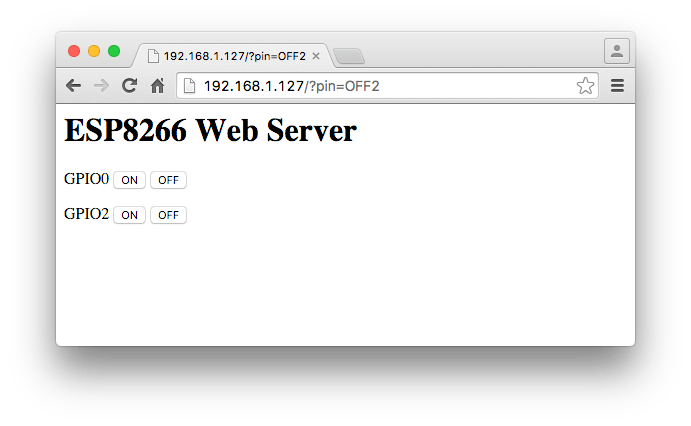 41 lines of code implements a webserver.
Firmware Comments
Bringing up the ESP8266 with the nodeMCU Lua software was a pretty good experience. Clearly a lot of functionality can be implemented with this  firmware. It supports timers, I2C, PWM, GPIO, the ADC and the serial UART. Pretty good and not too hard to get working. Once the software was running, we have had no problems with it at all.
I’ve read somewhere else that Analog pin was 0-1V not 0-1.8V
Yes and No. We’ve updated the web page to clarify things.
The Analog pin is 1.8V max on the pin! The ADC reads from 0 – 1024 over 0.0V to 1.0V.
That’s the confusion point.
SDL
I advise you to not use any of the outdated releases from https://github.com/nodemcu/nodemcu-firmware/releases. They’re old, unmaintained, suffer from memory issues and contain modules that you probably won’t need (but still eat memory. Use https://nodemcu-build.com/ or the Docker image at https://hub.docker.com/r/marcelstoer/nodemcu-build/ to build your own custom firmware from the NodeMCU dev branch. Disclaimer: both services are from yours truly.