
New Grove Dual WatchDog Timer Board Released
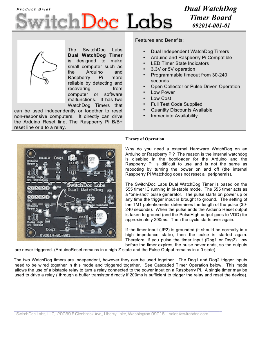
Why do you need a external Hardware WatchDog on an Arduino or Raspberry Pi? The reason is the internal watchdog is often disabled in the bootloader for the Arduino in some models and the Raspberry Pi is difficult to use and is not the same as rebooting by turning the power on and off (the internal Raspberry Pi Watchdog does not reset all peripherals). We added buffering to the latest version of the Dual Watchdog Timer which removes the requirement to set your inputs to high impedance and makes the Grove connector much easier to use.
Here is a recent series of articles by SwitchDoc Labs about WatchDog Timers and making your project more reliable.
The SwitchDoc Labs Grove/Pin Dual WatchDog Timer is based on the 555 timer IC running in astable mode. The 555 timer acts as a “continuous” pulse generator. The pulse starts on power up or any time the trigger input is brought to ground. The setting of the TM1 potentiometer determines the length of the pulse (30-240 seconds). When the pulse ends the Arduino Reset output is taken to ground (and the PulseHigh output goes to VDD) for approximately 200ms. Then the cycle starts over again.
If the timer input (JP2) is grounded (it should be normally in a high impedance state), then the pulse is started again. Therefore, if you pulse the timer input (Dog1 or Dog2) low before the timer expires, the pulse never ends, so the outputs are never triggered. (ArduinoReset remains in a high-Z state and the Pulse Output remains in a 0 state).
Version 110216-01-001 Note: Open Drain buffers were now added to the Grove Watchdog inputs. You no longer have to leave the inputs float for the watchdogs to operate. You can leave them float or set them high. It works both ways. This makes the WatchDog compatible with the Pi2Grover Raspberry Pi Grove board. If you want the previous behavior, you can connect up to JP1. The Dog1 and Dog2 inputs from JP1 are not buffered.
The two WatchDog timers are independent, however they can be used together. The Dog1 and Dog2 trigger inputs need to be wired together in this mode and triggered together. See Cascaded Timer Operation below. This mode allows the use of a bistable relay to turn a relay connected to the power input on a Raspberry Pi. A single timer may be used to drive a relay ( through a buffer transistor directly if 200ms is sufficient to trigger the relay and reset the device).
The SwitchDoc Labs Dual WatchDog Timer is designed to make small computer such as the Arduino and Raspberry Pi more reliable by detecting and recovering from computer or software malfunctions. It has two WatchDog Timers that can be used independently or together to reset non-responsive computers. It directly can drive the Arduino Reset line, the Raspberry Pi B/B+ reset line or a to a relay to reset a Raspberry Pi.
You can download the Dual WatchDog Product Brief here.
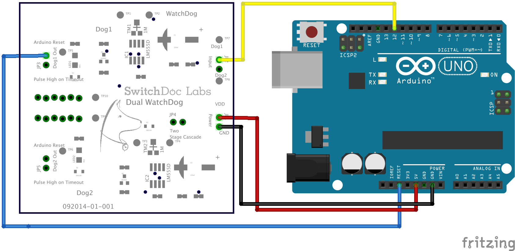
Below is how you hook it up to an Arduino.
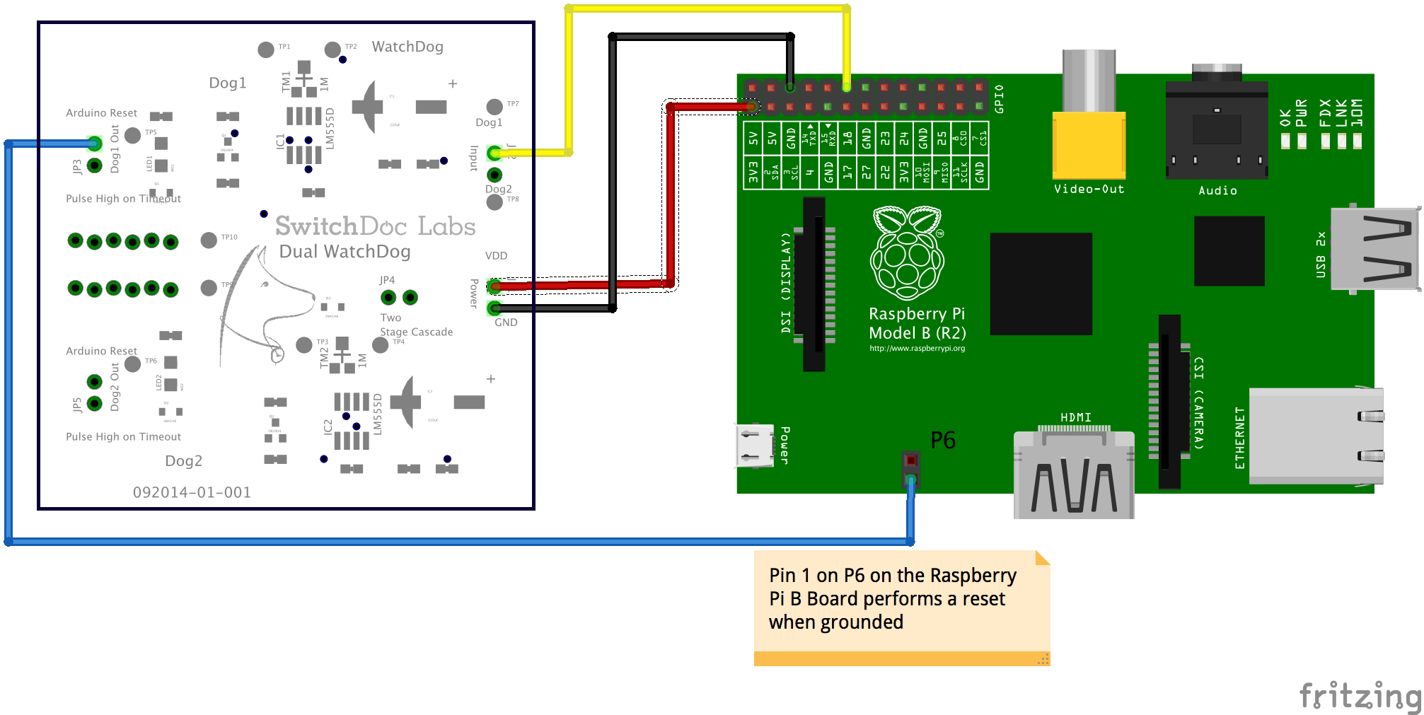
And here is how you hook it up to a Raspberry Pi B+.
Are these being included in the GroveWeatherPi Solar Add-on kits?
Yes they are. They just arrived and are being shipped now.
SDL