Grove/Pin Header I2C 4 Channel Mux Board w/Status LEDs ($17.95)
Comments are now closed. Please go to the Product Support Forum at the top of the page.
[include-page id=”buy-include-file”]
Features:
[list]
[list_item size=”small” icon=”icon-beaker” hex_color=””]Converts one I2C bus (on Pi or Arduino) to 4 seperate I2C buses[/list_item]
[list_item size=”small” icon=”icon-beaker” hex_color=””]All four I2C busses can be run at 3.3V or 5.0V, independently[/list_item]
[list_item size=”small” icon=”icon-beaker” hex_color=””]LEDs indicate the status of each I2C Bus – Great for debugging[/list_item]
[list_item size=”small” icon=”icon-beaker” hex_color=””]Pin Headers available for non Grove connections[/list_item]
[list_item size=”small” icon=”icon-beaker” hex_color=””]Has standard Grove connectors for easy connections[/list_item]
[list_item size=”small” icon=”icon-beaker” hex_color=””]Allows using same I2C addresses for many sensors galore![/list_item]
[list_item size=”small” icon=”icon-beaker” hex_color=””]Works with Arduino and Raspberry Pi[/list_item]
[list_item size=”small” icon=”icon-beaker” hex_color=””]Software Drivers for Arduino and Raspberry Pi Included![/list_item]
[list_item size=”small” icon=”icon-beaker” hex_color=””]Interrupt line on each channel[/list_item]
[list_item size=”small” icon=”icon-beaker” hex_color=””]100KHz / 400KHz operation[/list_item]
[list_item size=”small” icon=”icon-beaker” hex_color=””]On-board termination resistors for each channel![/list_item]
[/list]
This I2C Mux has GROVE connectors (as well as pin headers) and Status LEDs for each of the four channels.
[blockquote]
Really nice product!
I needed an I2C expander for my project, with multiple identical sensors that have set i2c addresses. I have seen other muxes, but this one fit the bill perfectly, just to be able to power the individual channels separately was the deciding factor. Connecting 3.3v and 5v sensors to an Raspberry Pi without much fuzz has made things easier. I bought two of these and I am considering buying some more, the version with the grove connectors looks tempting….-Andreas
[/blockquote]
The I2C 4 Channel Mux Breakout Board is a TCA9545A based quad bidirectional translating switch controlled via the I2C bus. The SCL/SDA controlling fans out to four downstream channels. It works for both the Arduino and  Raspberry Pi.
At SwitchDoc Labs, we love data. And we love I2C devices. We like to gather the data using lots of I2C devices on our computers and projects. Project Curacao has a total of 12, WeatherPi has 11 devices and SunRover will have over 20 and will require one I2C bus just for controlling the motors. We are always running into conflicts with addressing on the I2C device. Since there are no standards, sometimes multiple devices will have the same address, such as 0x70 and you are just out of luck in running both of them on the same I2C bus without a lot of jimmy rigging.
What is the solution for this? It’s an I2C controlled 4 I2C bus multiplexer!
And we have the software drivers written for it for the Arduino and the Raspberry Pi on
github.com/switchdoclabs. With the software and board, you are ready to go!
Specification and Documentation
The full specification for the Grove I2C 4 Channel Mux Breakout Board is available here.


Software Drivers
SwitchDoc Labs developed this pure Python TCA9545A I2CMux Raspberry Pi library and the Arduino Library and have posted them on the SwitchDoc Labs Respository on github.com
The Raspberry Pi Pure Python software is here: https://github.com/switchdoclabs/SDL_Pi_TCA9545
The Arduino Software is here: https://github.com/switchdoclabs/SDL_Arduino_TCA9545A
Theory of Operation
The TCA9545A is a quad bidirectional translating switch controlled via the I2C bus. The SCL/SDA controlling fans out to four 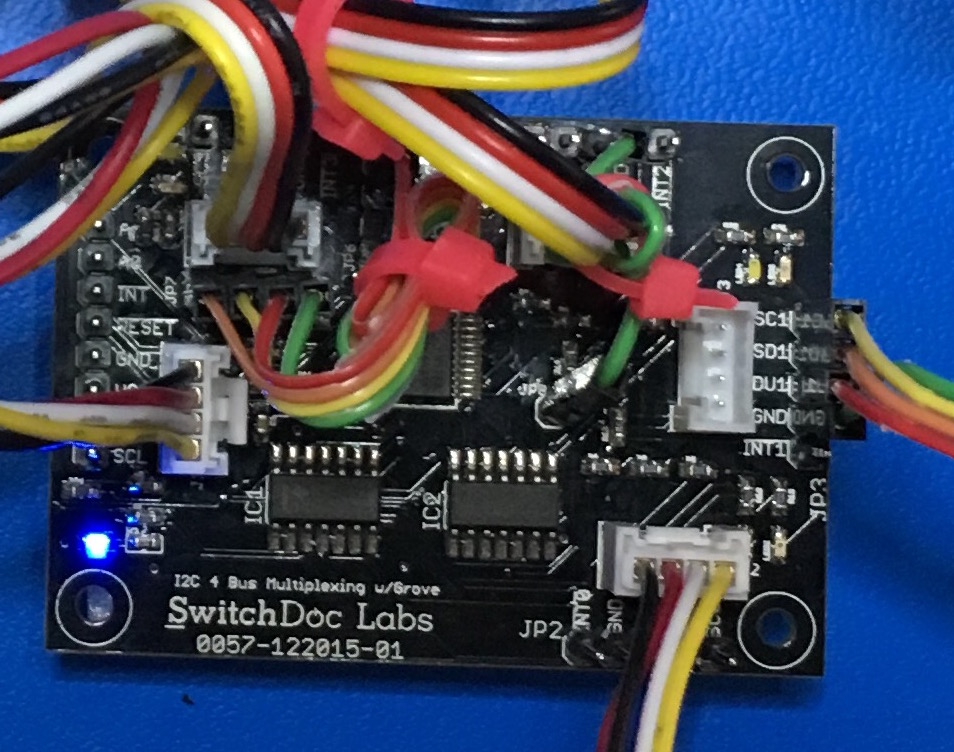 downstream channels. Any individual channel or combination of channels can be selected via I2C. Four interrupt inputs (INT3–INT0), one for each of the downstream pairs, are provided. One interrupt (INT) output acts as an AND of the four interrupt inputs. When you receive an interrupt, you read the interrupt register on the device to find out what channel interrupted you.
An active-low reset (RESET) input allows the TCA9545A to recover from a situation in which one of the downstream I2C buses is stuck in a low state. Pulling RESETlow resets the I2C state machine and causes all the channels to be deselected, as does the internal power-on reset function.
The TCA9545A allows the use of different bus voltages on each pair, so that 1.8-V, 2.5-V, or 3.3-V parts can communicate with 5-V parts, without any additional protection. External pull-up resistors pull the bus up to the desired voltage level for each channel. All I/O terminals are 5.5 V tolerant!
Wiring Examples
The Grove 4 Channel I2C Mux allows a mixture of 3.3V busses and 5.5V busses. The host bus voltages are set by connecting VCC on JP1 (or on the J1 connector) to 3.3V (for the Pi) or 5.0V (for the Arduino Uno for example). You then wire up the pins on JP6 to the desired 3.3V or 5.0V for the four slave busses.
If you are powering the I2C devices on a bus externally, then you can leave the corresponding pin of Jp6 (VDU0-3) unconnected. However, if you are powering the I2C from the Grove I2C Mux board, you must connect the Jp6 pins to the appropriate voltage levels. Remember to connect JP8 to the highest voltage you are using (note: 5V will always work on JP8).
Example 1:
Connected to the Raspberry Pi (3.3V) – all busses at 3.3V
| From | To | Description |
|---|---|---|
| Raspberry Pi GPIO Header / Pin 6 (GND) | Grove I2C Mux / JP1 Pin 4 (GND) | Ground |
| Raspberry Pi GPIO Header / Pin 1 (3.3V) | Grove I2C Mux / JP1 Pin 3 (VCC) | Power for Host Bus |
| Raspberry Pi GPIO Header / Pin 3 (SDA) | Grove I2C Mux / JP1 Pin 2 (SDA) | I2C SDA Data Pin |
| Raspberry Pi GPIO Header / Pin 5 (SCL) | Grove I2C Mux / JP1 Pin1 (SCL) | I2C SCL Clock Pin |
| Grove I2C Mux / JP7 Pin 1 (VCC) | Grove I2C Mux / JP6 Pin 1 (VDU0) | Sets Bus 0 to 3.3V (VCC) |
| Grove I2C Mux / JP7 Pin 2 (VCC) | Grove I2C Mux / JP6 Pin 2 (VDU1) | Sets Bus1 to 3.3V (VCC) |
| Grove I2C Mux / JP7 Pin 3 (VCC) | Grove I2C Mux / JP6 Pin 3 (VDU2) | Sets Bus 2 to 3.3V (VCC) |
| Grove I2C Mux / JP7 Pin 4 (VCC) | Grove I2C Mux / JP6 Pin 4 (VDU3) | Sets Bus 3 to 3.3V (VCC) |
| Raspberry Pi GPIO Header / Pin 17 (3.3V) | Grove I2C Mux / JP8 Pin 1 (VCCL) | Power for Buffers for LED |
Example 2:
Connected to the Raspberry Pi (3.3V) – Bus 0 and Bus 1 at 3.3V, Bus 2 and Bus 3 at 5.0V
| From | To | Description |
|---|---|---|
| Raspberry Pi GPIO Header / Pin 6 (GND) | Grove I2C Mux / JP1 Pin 4 (GND) | Ground |
| Raspberry Pi GPIO Header / Pin 1 (3.3V) | Grove I2C Mux / JP1 Pin 3 (VCC) | Power for Host Bus |
| Raspberry Pi GPIO Header / Pin 3 (SDA) | Grove I2C Mux / JP1 Pin 2 (SDA) | I2C SDA Data Pin |
| Raspberry Pi GPIO Header / Pin 5 (SCL) | Grove I2C Mux / JP1 Pin1 (SCL) | I2C SCL Clock Pin |
| Grove I2C Mux / JP7 Pin 1 (VCC) - 3.3V | Grove I2C Mux / JP6 Pin 1 (VDU0) | Sets Bus 0 to 3.3V (VCC) |
| Grove I2C Mux / JP7 Pin 2 (VCC) | Grove I2C Mux / JP6 Pin 2 (VDU1) | Sets Bus1 to 3.3V (VCC) |
| Raspberry Pi GPIO Header / Pin 2 (5.0V) | Grove I2C Mux / JP6 Pin 3 (VDU2) | Sets Bus 2 to 5.0V |
| Raspberry Pi GPIO Header / Pin 4 (5.0V) | Grove I2C Mux / JP6 Pin 4 (VDU3) | Sets Bus 3 to 5.0V |
| Raspberry Pi GPIO Header / Pin 4 (5.0V) | Grove I2C Mux / JP8 Pin 1 (VCCL) | Power for Buffers for LED |
Example 3:
Connected to the Arduino Uno (5.0V) – Bus 0 and bus 1 at 5.0V, Bus 2 and Bus 3 at 3.3V
| From | To | Description |
|---|---|---|
| Arduino Uno Power / GND | Grove I2C Mux / JP1 Pin 4 (GND) | Ground |
| Arduino Uno Power / 5V (VCC) | Grove I2C Mux / JP1 Pin 3 (VCC) | Power for Host Bus |
| Arduino Uno Analog In / A4 - SDA | Grove I2C Mux / JP1 Pin 2 (SDA) | I2C SDA Data Pin |
| Arduino Uno Analog In / A5 - SCL | Grove I2C Mux / JP1 Pin1 (SCL) | I2C SCL Clock Pin |
| Arduino Uno Power / 3.3V | Grove I2C Mux / JP6 Pin 1 (VDU0) | Sets Bus 0 to 3.3V (VCC) |
| Arduino Uno Power / 3.3V | Grove I2C Mux / JP6 Pin 2 (VDU1) | Sets Bus1 to 3.3V (VCC) |
| Grove I2C Mux / JP7 Pin 3 (VCC) | Grove I2C Mux / JP6 Pin 3 (VDU2) | Sets Bus 2 to 5.0V |
| Grove I2C Mux / JP7 Pin 4 (VCC) | Grove I2C Mux / JP6 Pin 4 (VDU3) | Sets Bus 3 to 5.0V |
| Arduino Uno Power / 5V | Grove I2C Mux / JP8 Pin 1 (VCCL) | Power for Buffers for LED |
Test Results
Using the Arduino libraries and the test software show the following result. The test setup is to connect an additional I2C device to Bus 0 – in this case a SwitchDoc Labs INA3221 Breakout Board at address 0x40 on Bus0.
-----------------------------
------------------------------
SDA_Arduino_TCA9545_Test
Reading all four I2C Buses
------------------------------
------------------------------

------------------------------
------------------------------
Bus 0 Control Register:1
Scanning...
I2C device found at address 0x40  !
I2C device found at address 0x73  !
done

------------------------------
Bus 1 Control Register:2
Scanning...
I2C device found at address 0x73  !
done

------------------------------
Bus 2 Control Register:4
Scanning...
I2C device found at address 0x73  !
done

------------------------------
Bus 3 Control Register:8
Scanning...
I2C device found at address 0x73  !
done
Repeat the above test connecting the I2C Device to Bus1, Bus2 and Bus3
The I2C device (the INA3221 in this case) will move from bus to bus.