SwitchDoc Labs Dual WatchDog Timer
[include-page id=”buy-include-file”]
![[include-page id=”buy-include-file”]](https://www.switchdoc.com/wp-content/uploads/2014/10/IMG_1232.jpg)
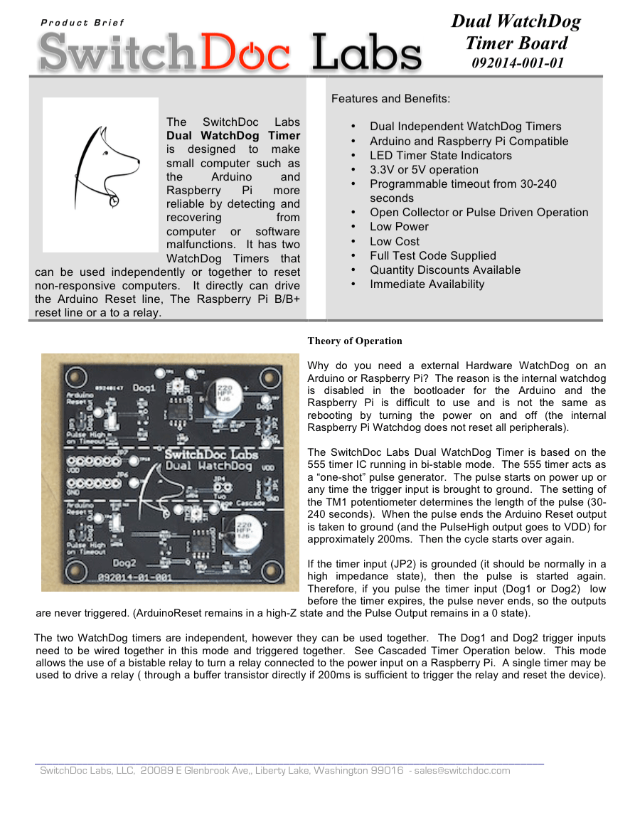
 Production Dual WatchDog Board
Why do you need a external Hardware WatchDog on an Arduino or Raspberry Pi? The reason is the internal watchdog is disabled in the boot loader for the Arduino and the Raspberry Pi watchdog is unreliable and difficult to use.
The SwitchDoc Labs Dual WatchDog Timer is designed to make small computer such as the Arduino and Raspberry Pi more reliable by detecting and recovering from computer or software malfunctions. It has two WatchDog Timers that can be used independently or together to reset non-responsive computers. It directly can drive the Arduino Reset line, the Raspberry Pi B/B+ reset line or a to a relay to reset a Raspberry Pi.
Version 110216-01-001 Note: Open Drain buffers were now added to the Grove Watchdog inputs. You no longer have to leave the inputs float for the watchdogs to operate. You can leave them float or set them high. It works both ways. This makes the WatchDog compatible with the Pi2Grover Raspberry Pi Grove board. If you want the previous behavior, you can connect up to JP1. The Dog1 and Dog2 inputs from JP1 are not buffered.
Version 032116-01-001 Note: that your Grove Connector on your computer must be capable of being able to “float” (i.e. be an input) for the watchdog to work. If it does not float, then you must connect the Triggers directly to a GPIO on your computer.
Here is a recent series of articles by SwitchDoc Labs about WatchDog Timers.
You can download the Dual WatchDog Product Brief here.
Comments are now closed. Please go to the Product Support Forum at the top of the page.
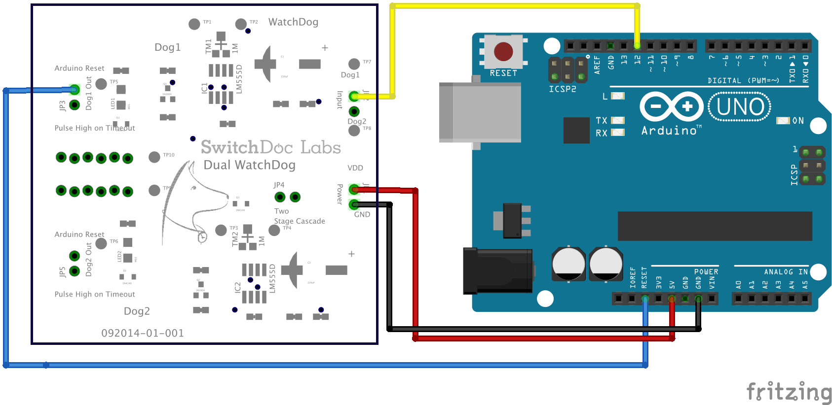
Below is how you hook it up to an Arduino.
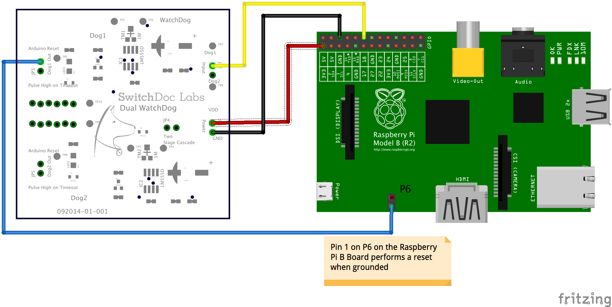
And here is how you hook it up to a Raspberry Pi B+.
Can I use this board to set up 2 Pi’s or Arduino’s as a redundant pair that is master standby to switch if one is in fault?
Yes, definitely. You will need to power down the faulted module. You can use our USB PowerController to do that.
SDL
We have a doubt that our Raspberry will be again avilable after 4 min. In most cases this is enough time but in some cases not. Would it be possible to have a device with a longer delay ?
Thanks
Alessandro,
Almost invariably, the Raspberry Pi will boot up with in 4 minutes. However, I understand your concern. Here are two things you can do:
1) Unsolder the trim pot and replace it with a 2M Ohm trimpot or resistor. That will take it up to about ~8 minutes
2) Go into your local.rc file or the boot up files itself on the Raspberry Pi and insert a function that will “pat the dog” much earlier in the boot process than when your userspace program is run. This will work. Search on “boot up files Raspberry Pi” or “Bootup process on Raspberry Pi”.
Best,
SDL
This seems to work fine on the arduino uno but it seems to instantly keep resetting the arduino mega.
The LED1 on the Watchdog keeps flashing. Any ideas?
Hi Tom,
My guess is you aren’t “patting the dog” on your Arduino Mega or you have connected the wrong WatchDog output (the pulse rather than the open drain output). We use these boards all the time with the ArduinoMega.
Try checking your wiring very carefully.
SDL
Hi can the two halves of the board be physically separated for use on different projects? They kind of look like perf lines but I only see one power/gnd header unless the bus on the left can fill in once divided?
Hi Dave,
No, they really can’t be cut. We have been asked to do that and will for the next revision of the board. Thanks for the comment.
SDL
Hello,
Very interesting product here. I use on my raspberry pi a power button from MSL Digital Solutions. This button board uses the following pins:
2,4,6.8.9,10 and 12
Would I be able to use your dual watchdog timer using pins other than the ones my button daughterboard are using?
Thank you.
Yes, you can use any GPIO pins for the WatchDog timer.
Best regards,
SDL
Thanks very much for the reply. So this board has a firmware on it to set which pin to use to hard reset the frozen Pi? If so how do we interact with it to set the timeout limit.
Also, I’m trying to understand how this board connects with the Pi itself. Does it require soldering? Is it mounted (affixed) in some way to the top of the Pi? I’m trying to find pictures of your board connected to a Pi but they are all conceptual drawings and not actual real pictures of how it would look together.
Thank you.
Using the WatchDog Dual Timer; it constantly resets the Arduino Mega. LEDS are both on steady, red.
Starting server: 12/30/2015 , 19:58:19
Starting server: 12/30/2015 , 19:59:40
Starting server: 12/30/2015 , 20:01:00
Starting server: 12/30/2015 , 20:02:29
Starting server: 12/30/2015 , 20:02:48
Starting server: 12/30/2015 , 20:03:42
Starting server: 12/30/2015 , 20:05:02
Starting server: 12/30/2015 , 20:05:37
Starting server: 12/30/2015 , 20:06:26
Starting server: 12/30/2015 , 20:07:14
Starting server: 12/30/2015 , 20:08:02
Starting server: 12/30/2015 , 20:08:50
Starting server: 12/30/2015 , 20:09:38
Starting server: 12/30/2015 , 20:10:13
Starting server: 12/30/2015 , 20:10:27
Starting server: 12/30/2015 , 20:13:03
Have tried min and max trim resistor settings; as you can see above.
How do I “pat the Dog?” Do I need to call the function? I see no reference in the product brief to calling the function.
#define RESET_WATCHDOG1 6
void ResetWatchdog1()
{
pinMode(RESET_WATCHDOG1, OUTPUT);
delay(200);
pinMode(RESET_WATCHDOG1, INPUT);
Serial.println(“Watchdog1 Reset”);
}
Thank you for producing the WatchDog Dual Timer!
William
Trying to use the WatchDog Dual Timer to only restart server when defined pin 6 goes to 0 volt
Hi William,
Yes, you need to pat the dog! You need to put the function call in your main loop and make sure it is called every 30 seconds or so (according to your email).
If you don’t, then the mega is reset as above.
Take a look at this article:
https://www.switchdoc.com/2014/11/reliable-projects-5-external-watchdog-timers-raspberry-piarduino-systems/
Best regards,
SDL
Hi, could you share your fritzing model for this board? I would like to generate a couple layouts my project documentation.
Dave,
We will be happy to do that. We will add that onto the product page next week.
Best regards,
SDL
I am using the ebl-arduino/RTCEventTimer library to call ResetWatchdog1() every one minute; without interfering the main loop
William,
Here is what I would suggest. Add a print statement in the reset watchdog code to make sure it is being called. If it is being called, check the output pin that is going to the watchdog to make sure it is working correctly. It could be a software or wiring issues.
Best regards,
SDL
Output voltage from Arduino Mega (Digital Pin 6 on JP2) reads 3.3 V when pulse is HIGH. Print statements confirm RESET_WATCHDOG1 is being called. every one minute.
What is the best way to set the trim pot (TR1)?
What is the purpose of TP1-8? Test points?
Hi William,
Pin 6 needs to be in hi-Z mode when it is not being actively pulsed. Would you post the code you are using for patting the dog?
Look in the spec at the diagram of the trim pot. You can use a jewelers screwdriver to turn the pot to the desired position.
TP1-TP8 are test points for testing the function of the device in production.
Best regards,
SDL
William,
Thank you for sending me the code. Nice use of the RTCTimedEvent.h code. I like it.
It looks good, except one thing is bothering me. Pin 6 needs to be pulsed Low and then returned to Hi-z (by turning it to an input). You say that it is at 3V when pulse is HIGH? That doesn’t make sense to me.
Is it possible you have set the value of the GPIO pin to 1 somewhere in the code? Explicitly set it to 0 and see if that fixes it.
Best regards,
SDL
Measuring 4 volts when patting the Dog. Rest of the time ~.3 Volt.
https://tinyurl.com/folder500 –Folder contains my project code and Example code –RTCEventTime library.
William
William, It should be 0.0V when patting the dog. It is floating the the rest of the time so measuring the voltage won’t work well.
What pin do you have it plugged into the WatchDog?
SDL
Try adding a statement in setup to initialize the GPIO to a “0”.
SDL
would love to see a small foot print, single watchdog, line header bread-boardable version of this. random .02
Voltage readings were taken without any connection at the pin (normally going to Watchdog1 Input) and referenced to ground. I could see voltage go from a High to a low; whenever, the RESET_WATCHDOG1 function was called within the running SdBrowse_Ethernet_WebServer.ino Sketch.
Changed the delay to 5000, to more easily see voltage change. Change delay back to 200 in the RESET_WATCHDOG1 function when finished reading voltages.
If the “pulse” at the input of Watchdog1 is missing –does this causes a Low voltage to be pulsed at the Watchdog1 output; resetting the Arduino?
How can the Output pulsing of the Watchdog1 Output be tested? Trying to find right duration of the LOW Watchdog1 output. I think I have adjusted for it correctly; would like to confirmed the setting works.
William
William,
If you remove the lines attached to the DOG1_TRIGGER and DOG2_TRIGGER, the Watchdog board will start trying to reboot the attached devices. You will see the LEDs flash periodically (time depends where you have set the trim pot). That is how you test the output.
If that test works, then connect up your GPIO signal and see if it changes the flashing behavior.
Best regards,
SDL
Thank you for all the help. Working as described in the documentation. Perfect!!!
William
William,
Glad to hear. To help others, what did the problem turn out to be?
SDL
Problem was I did not allow enough time for the Trim POT, time to expire and change the state of the LED from “ON” to “OFF.” Allowing approximately three minutes; the LED changed state from “ON” to “OFF.”
Thank you for producing the SwitchDoc Labs, “Watchdog Dual Timer.”
William
Hi,
very interesting board.
What are the overall dimension of the board and
what is the spacing of the mounting holes?
Daniel
Hi Daniel,
Physical dimensions of board: 63.44mm x 64.33mm x 12mm(max). Mounting holes inset 3.5mm x3.5mm from each corner
Best Regards,
SDL
Hi,
I’m trying to get the Dual WatchDog Board working with my Raspberry Pi 2B. If I connect the power and ground both LEDs on the WatchDog will light up solid and then blink periodically. But when I connect the input and output leads to the rpi I never get a blink on WatchDog 1. WatchDog 2 continues to blink periodically. I’m not doing anything with GPIO 18 at this point with my software, I just want to see it resetting the rpi before I try to get the “dog pat” process working in my software.
Any ideas what I’m doing wrong?
Thank you.
Jim
It sounds like GPIO18 is being pulled up or down. You need to make sure that it is “floating”, i.e. programmed as an input with no pull-ups or pull downs.
In python: GPIO.setup(RESET_WATCHDOG1, GPIO.IN)
Add that to your code.
Best regards,
SDL
My program is written in Java and I’m using pi4j. I was struggling to get any results that made sense, so I finally backed off the Java and experimented with Python using your code snippet and other examples that are easy to find on the web. I got expected results with Python after the realization that I needed to use GPIO.setmode(GPIO.BCM) which got me thinking about the port numbering scheme being used by pi4j. So I wrote a Java test program using an LED and discovered that the pin labeled GPIO_18 on the Raspberry Pi 2 Model B is referenced as GPIO_01 in pi4j. Go figure. My WatchDog is working fine now, and I’m posting my Java code here for reference. Thank you.
import com.pi4j.io.gpio.GpioController;
import com.pi4j.io.gpio.GpioFactory;
import com.pi4j.io.gpio.GpioPin;
import com.pi4j.io.gpio.GpioPinDigitalOutput;
import com.pi4j.io.gpio.PinMode;
import com.pi4j.io.gpio.PinPullResistance;
import com.pi4j.io.gpio.PinState;
import com.pi4j.io.gpio.RaspiPin;
private void patDog() {
GpioController gpio = GpioFactory.getInstance();
GpioPin pin = gpio.provisionPin(RaspiPin.GPIO_01, “GPIO_01”,PinMode.DIGITAL_OUTPUT );
pin.setMode(PinMode.DIGITAL_OUTPUT);
((GpioPinDigitalOutput)pin).setState(PinState.LOW);
Thread.sleep(200);
pin.setMode(PinMode.DIGITAL_INPUT);
pin.setPullResistance(PinPullResistance.OFF);
return;
}
Jim,
We have fought with the GPIO numbering schemes since we started using the Raspberry Pi years ago. I wonder how many man-hours have been lost by their decision to support both?
Good code.
Best,
SDL