
Tutorial: Connecting an Arduino to the 433MHz WeatherRack2

SwitchDoc Labs has now released a custom built set of WeatherSense 433Mhz Wireless Weather Sensors called the WeatherRack2 for you to build your own weather station using Raspberry Pi’s, Arduino or ESP32 based computers. Your pick! We are using some really advanced technology and software such as using a Software Defined Radio (SDR) in the Raspberry Pi kits to get really good quality data from the wireless sensors. This project will also receive the data from the SDL F016TH Indoor Temperature / Humidity Sensor.

Connecting the Arduino to the 433MHz WeatherRack2
The Arduino UNO is the best board to get started with electronics and coding. It is simple, fully contained and there are thousands of projects out there to build using an Arduino. It is based on the ATmega328P processor and has 14 digital input/output pins and 6 analog inputs. This kit uses only one digital input so you have lots of other pins to use on your own projects. The range of these units will be around 50-100 meters depending on your electrical environment and where you locate the receiver. You can increase the range by using better antennas that the suggested Dipole antenna.
This post provides step by step instructions for installation, operation and troubleshooting an Arduino receiver for the WeatherRack2.

First Step
Assemble your WeatherRack2 and Indoor T/H Sensor and put batteries in the units. Follow the instructions in the WeatherRack2 Technical Specification and Assembly manual.
Required Parts

Part A – 3 male to female jumpers
Part B – Arduino UNO – Any Arduino or compatible will work. You can use a Arduino Mega or Pro Mini. ( https://amzn.to/3pdOrX0 )
Part C – 2 female 17cm dipole antenna cable (colors will vary) Cut two jumpers to 17cm long and leave the female header attached
Part D – RXB6 433Mhz Receiver – ( https://amzn.to/3lpvluJ )
Part E – USB Cable for Arduino to Computer Connection (included in the Arduino link above in Part B)
Step-By-Step Assembly
Step 1 – Plug the 3 male to female jumpers (Part A) into the GND, Data and +5V pins of the RXB6 receiver (Part D) . Carefully note the colors that you have on each pin (your colors will vary).

Step 2 – Plug the Two Lead Female Dipole antenna (Part C) into the RXB8 (Part D) pins ANT and GND as shown. Separate the wires.

Step 3 – Plug the male end of the 3 male to female jumpers (Part A) into the Arduino Uno (Part B) pins as follows:
| RXB8 (Part D) Pins | Arduino UNO (Part B) Pins |
| GND | GND |
| DATA | Pin 8 |
| +5V | 5V |

Check your work! DO NOT MIX UP THESE WIRES! YOU MAY DAMAGE YOUR HARDWARE!
Step 4 – Plug the square end of the USB Cable (Part E) in the Arduino UNO (Part B) and then the other end of the USB Cable into an USB Port on your computer.
Installing the Software
The Arduino UNO (Part B) is generally supplied unprogrammed. To program the Arduino, you must install the Arduino IDE, download the software and program the Arduino. Before you proceed, make sure you have assembled your WeatherRack2 and have batteries in both the WeatherRack2 and the Indoor T/H Sensor (F016TH).
Step 1 – Install the Arduino IDE on your computer. This process will vary according to your computer. Go to
https://www.arduino.cc/en/Guide
and follow the instructions for your computer.
Step 2 – Download the SDL_Arduino_WeatherRack2 drivers.
Go to:
https://github.com/switchdoclabs/SDL_Arduino_WeatherRack2
and download the zip file (under the green Code tab).
Step 3 – Unzip the downloaded file
Step 4 – Remove the “-master” from the name of the unzipped directory
Step 5 – Move the whole program directory to your “arduino” directory. The location of this will vary by computer type.
Step 6 – Open up the Arduino IDE
Step 7 – Select the Arduino Board you have. Go to Tools->Board->Arduino AVR Boards->Arduino UNO

Step 8 – Select the USB Serial port in which you have plugged the Arduino. Go to Tools->Port->(select your UNO). The port number and name will vary by computer type.
Step 9 – Open the downloaded SDL_Arduino_WeatherRack2.ino file. Go to Open->SDL_Arduino_WeatherRack2 and select the SDL_Arduino_WeatherRack2.ino file.
Step 10 – Now you will see three tabs containing the WeatherRack2 software.
Step 11 – Click on the magnifying glass on the upper right of the Arduino IDE to see the Serial output from the Arduino.
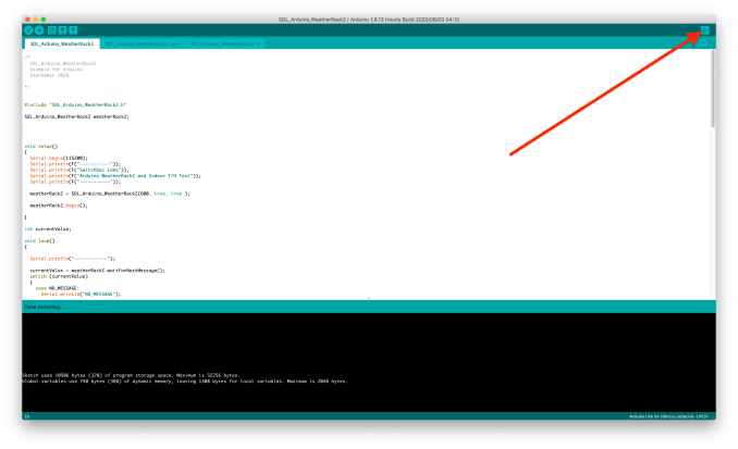
Next set your Serial Window Baud Rate to 115200

Step 12 – Compile and download the code to your Arduino by hitting the green right facing arrow button on the upper left of the Arduino IDE screen.
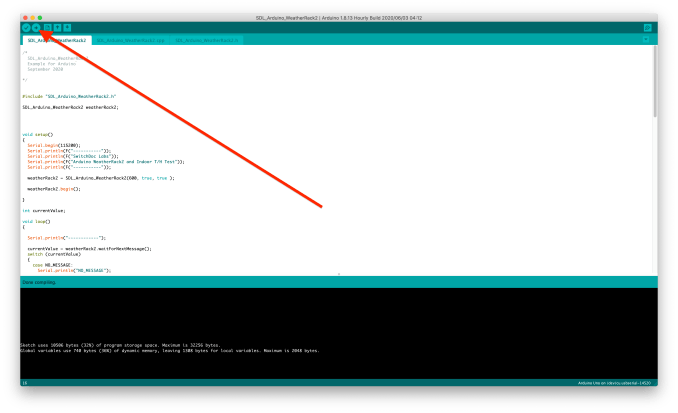
You will see lights flashing on your Arduino UNO and you should see text starting up in your Serial port.
12:58:59.684 -> ------------
12:59:01.646 -> -----------
12:59:01.646 -> SwitchDoc Labs
12:59:01.646 -> Arduino WeatherRack2 and Indoor T/H Test
12:59:01.646 -> -----------
12:59:01.646 -> ------------
And eventually (after a minute or so) you should start to see data coming in.
13:12:38.612 -> ------------
13:12:44.963 -> -----------
13:12:44.963 -> SwitchDoc Labs
13:12:44.963 -> Arduino WeatherRack2 and Indoor T/H Test
13:12:44.963 -> -----------
13:12:44.963 -> ------------
13:12:51.786 ->
13:12:51.893 -> MESSAGE_WEATHERRACK2_GOOD
13:12:51.893 ->
13:12:51.893 -> currentWR2.messageid=1
13:12:51.893 -> currentWR2.time=
13:12:51.893 -> currentWR2.device=12
13:12:51.893 -> currentWR2.modelnumber=0
13:12:51.893 -> weatherRack2.currentWR2.battery=0
13:12:51.893 -> currentWR2.avewindspeed=12.00
13:12:51.893 -> currentWR2.gustwindspeed=26.00
13:12:51.893 -> currentWR2.winddirection=259
13:12:51.893 -> currentWR2.cumulativerain=1920
13:12:51.893 -> currentWR2.temperature=0.50
13:12:51.893 -> currentWR2.humidity=79
13:12:51.926 -> currentWR2.light=3705
13:12:51.926 -> currentWR2.uv=0
13:12:51.926 -> currentWR2.CRC=0x20
13:12:51.926 ->
13:12:51.926 -> Headers Found=1
13:12:51.926 -> WeatherRack2 Sensors Found=1
13:12:51.926 -> Indoor T/H Found=0
13:12:51.926 ->
13:12:56.910 -> ------------
13:13:00.697 ->
13:13:00.732 -> MESSAGE_INDOORTH_GOOD
13:13:00.732 ->
13:13:00.732 -> IndoorTHMessage.messageid=2
13:13:00.732 -> IndoorTHMessage.time=
13:13:00.732 -> IndoorTHMessage.device=249
13:13:00.732 -> IndoorTHMessage.modelnumber=5
13:13:00.732 -> IndoorTHMessage.channel=3
13:13:00.732 -> IndoorTHMessage.battery=0
13:13:00.732 -> IndoorTHMessage.temperature=21.00
13:13:00.768 -> IndoorTHMessage.humidity=32
13:13:00.768 -> IndoorTHMessage.CRC=0x44
13:13:00.768 ->
13:13:00.768 -> Headers Found=2
13:13:00.768 -> WeatherRack2 Sensors Found=1
13:13:00.768 -> Indoor T/H Found=1
13:13:00.768 ->
13:13:05.748 -> ------------
Congratulations. You are connected to the WeatherRack2 Sensors!
Here is a video of the unit working:
Notes on Radio Reception
Your computer, monitors, cell phone can generate interference for your Arduino Kit.
Wireless communication is susceptible to interference, distance, walls and metal barriers. We recommend the following best practices for trouble free wireless communication.
- Electro-Magnetic Interference (EMI). Keep the sensors several feet away from computer monitors and TVs.
- Radio Frequency Interference (RFI). If you have other 433 MHz devices and communication is intermittent, try turning off these other devices for troubleshooting purposes. You may need to relocate the transmitters or receivers to avoid intermittent communication.
- Line of Sight Rating. This device is rated at 100 m line of sight (no interference, barriers or walls) but typically you will get 30 m maximum under most real-world installations, which include passing through barriers or walls.
- Metal Barriers. Radio frequency will not pass through metal barriers such as aluminum siding. If you have metal siding, align the remote and receiver through a window to get a clear line of sight.
The following is a table of reception loss vs. the transmission medium. Each “wall”or obstruction decreases the transmission range by the factor shown below.
| Medium | RF Signal Strength Reduction |
| Glass (untreated) | 5-15% |
| Plastics | 10-15% |
| Wood | 10-40% |
| Brick | 10-40% |
| Concrete | 40-80% |
| Metal | 90-100% |
About the Technology
The engineering on this project was great fun for the whole engineering team. Others handled the sensors and our manufacturers, but I was tasked with figuring out how to receive (demodulate) all the incoming 433MHz signals from the WeatherSense sensors. It was a heck of a challenge!
The first thing we did was to learn how to use a Software Defined Radio (SDR) on the Raspberry Pi. We started analyzing the signals coming into the antenna and figuring out what was going on. We had the digital data formats from our manufacturing partners but what it looks like coming in over radio waves was quite another challenge. We first decoded the simpler Indoor Temperature / Humidity Sensor (making sure we used the proper CRC checksum to guarantee correct reception – 433MHz is noisy and there are lot of other things on the frequency band such as your car key, garage door openers, etc., etc.). We used as a starting step a variety of tools on our Raspberry Pi (RF_Hacker and rtl_433 for two) and started to match the signals coming from the SDR to the digital bits. The coding uses something called Manchester Encoding which makes it difficult to read the signal data with just the eye. We wrote software to decode it and after a lot of effort, we were reading the Indoor Sensor and the WeatherRack2 correctly from the Raspberry Pi using our Software Defined Radio.

Next, we had to do the Arduino drivers. No help with a Software Defined Radio on this platform. We had to read in the encoded data (from a simple receiver, the RXB6 – we chose this receiver after testing about 10 different ones. Great value and reception for the cost) and look at the timing down on the order of about 200 usec. That is 200 millionths of a second! Using a Saleae Logic Analyzer, we figured out what parts were what and then wrote and modified software to get the data out of our sensors using an Arduino (which is a tiny computer compared to the Raspberry Pi!). Whew! One very odd thing we found out this way was the each Indoor Temperature/Humidity message sent each message three times, with no gaps (see picture) and our WeatherRack2 sent each message twice with a gap. Explained why we would pick up multiple transmissions with the Raspberry Pi SDR!